10M WATER METER (Ultrasonic Water Meter S10F, modification 10M, Mains powered with Power backup)
S10F – main powered industrial water meters designed to measure all the necessary parameters of water consumption. Devices measure volume, mass, excessive pressure of water or liquids with solids (not more than 200 mkm).
The device allows to ensure heat and water accounting (cold and hot) at the same time. Devices measure volume, mass, excessive pressure of water or liquids with solids (not more than 200 mkm).
- Accuracy degree – class 1, 2 (depends on performance);
- Case material – stainless steel 20;
- Connection – flange;
- DN – 20 mm – 1200 mm;
- Powering – cable (there is backup battery 14 hours working);
- Service life – not less than 12 years;
- Warranty – 4 years.
Description
The device is used for large scale diameters of pipes. More often we can see it on:
- enterprises
- educational institutions or kindergartens
- thermal and nuclear power plants
- administrative buildings and hospitals
SVTU-10 M equipped with multistage protection system that used against falsifications. Availability of archives for data saving (hourly, daily, monthly, yearly) ensures comfortable device service.
Industrial meters have a range of features:
- the device has connection with two channels of flow measurement and with five temperature measurement channels. In addition, it has connection with two temperature and 2 pressure sensors and with two external flow meters (with impulse outputs).
- there is heat and water accounting with possibility of automatic switching mode.
- backup flow sensors are mandatory available. It is about big flow meters with diameter over then 150 mm. Backup flow sensors allow to change useless flow sensors without break.
- we ensure all cables and sensors sealing. It's made for protection against atmospheric effects of moisture and emergency flooding.
- sluice construction of the sensors allows to provide installation and repairing under pressure without flow stop in a pipeline.
- wide self-diagnostic possibilities ensure data saving and printing. It can indicate more than 40 possible defects during heat accounting inside and outside the accounting node.
- the device measures both flow directs.
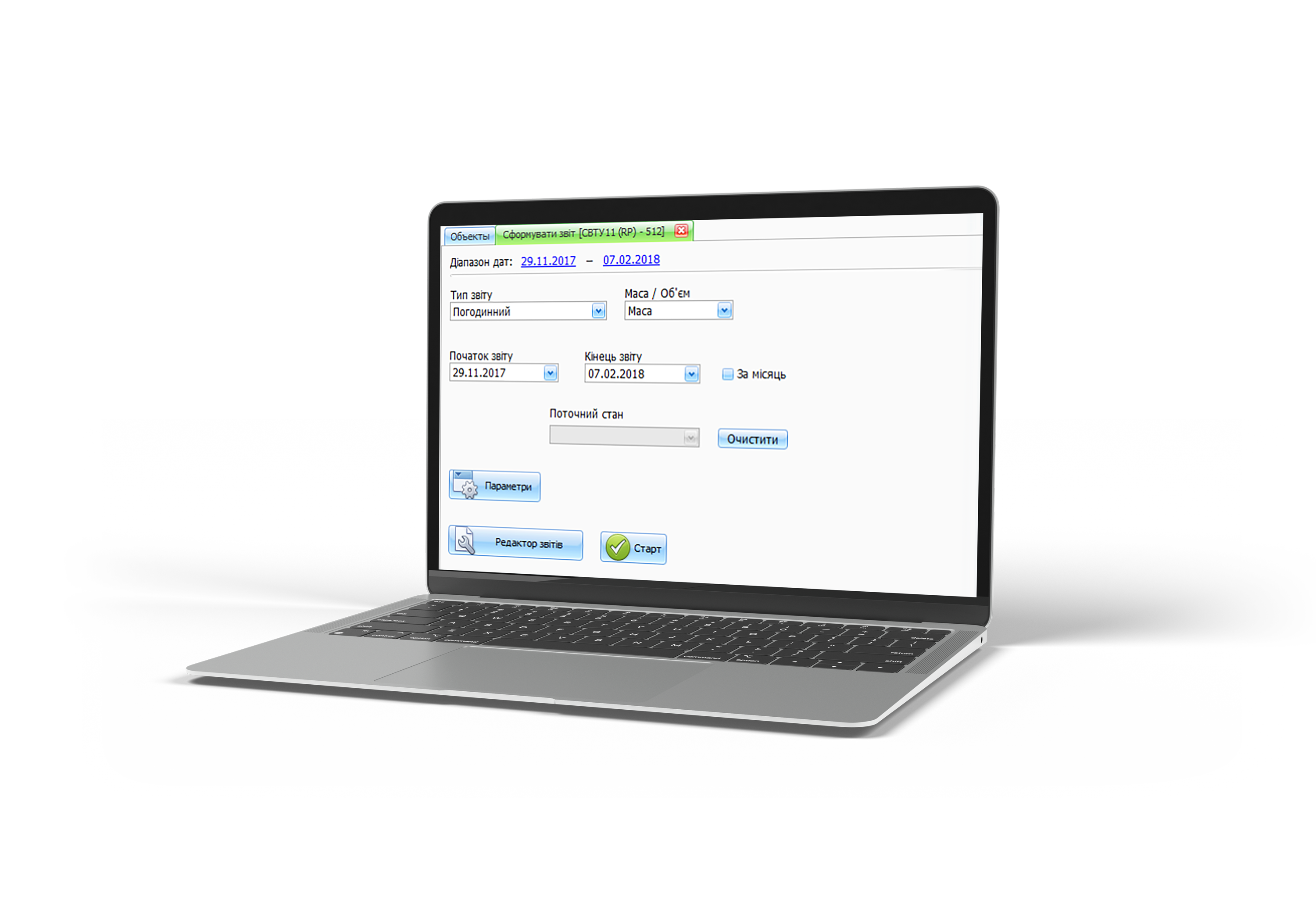
- free software has reading possibility to PC or Android.
- besides the usually mechanical plug we used electronic sealing with passwords for reliable protection against falsifications and unauthorized access. In addition, device has events and moments fixing. It has input/output reasons fixing to.
To get more information about equipment and performance options contact us by phone numbers:
Technical specifications
|
Measurement unit: |
Due the installation you can choose: Thermal power displayed by units: |
|
Temperature range of heat carrier |
2…150 °C |
|
Temperature difference range of heat carrier |
3…150 °C |
|
Environment temperature range of heat carrier |
5…55 °C |
|
Pressure PN, kgs/cm2 |
16 bar (for DN20 – DN1200); |
|
Battery |
Has a 14 hour backup battery |
|
Power supply |
From the network |
|
Data reading |
RS 232 built-in. |
|
Display |
LCD, 8 categories + text row |
|
Materials |
Flow meter section: |
|
Protection degree |
Computer case – IP65; |
|
Accuracy degree (by EN1434) |
Class 1, Class 2 |
|
Environment degree for device working |
"C" by EN1434: |
|
Archiving |
The device accumulates the following types of archives: |
|
Maximum power and flow rates |
Accounting of maximum values based on average values for fixed period of time. Possible average interval is from 1 minute to 30 minutes. |
|
Temperature sensors |
Depends on order. |
|
Type of flowmetering section (FMS) |
Minimum flowrate Q1, m3/h |
Ttransitional flowrate Q2, m3/h |
Permanent flowrate Q3, m3/h |
Overload flowrate Q4, m3/h |
R |
Pressure loss class Δp |
FMS connection |
L, mm |
|
DN20 |
0,063 |
0,101 |
6,3 |
7,875 |
100 |
Δp25 |
G 1 B |
160 |
|
DN25 |
0,100 |
0,16
|
10 |
12,5 |
100 |
Δp25 |
G 1 B |
160 |
|
DN32 |
0,25 |
0,4 |
25 |
31,25 |
100 |
Δp40 |
Flange DN32PN16 |
180 |
|
DN40 |
0,4 |
0,64 |
40 |
50 |
100 |
Δp40 |
Flange DN40PN16 |
200 |
|
DN50 |
0,63 |
1,008 |
63 |
78,75 |
100 |
Δp40 |
Flange DN50PN16 |
180 |
|
DN65 |
1 |
1,6 |
100 |
125 |
100 |
Δp40 |
Flange DN65PN16 |
200 |
|
DN80 |
1,6 |
2,56 |
160 |
200 |
100 |
Δp40 |
Flange DN80PN16 |
210 |
|
DN100 |
2,5 |
4 |
250 |
312,5 |
100 |
Δp40 |
Flange DN100PN16 |
230 |
|
DN125 |
4 |
6,4 |
400 |
500 |
100 |
Δp10 |
Flange DN125PN16 |
265 |
|
DN150 |
6,3 |
10,08 |
630 |
787,5 |
100 |
Δp10 |
Flange DN150PN16 |
315 |
|
DN200 |
10 |
16 |
1000 |
1250 |
100 |
Δp10 |
Flange DN200PN16 |
540 |
|
DN250 |
25 |
40 |
2500 |
3125 |
100 |
Δp10 |
Flange DN250PN16 |
620 |
|
DN300 |
25 |
40 |
2500 |
3125 |
100 |
Δp10 |
Flange DN300PN16 |
680 |
|
DN350 |
40 |
64 |
4000 |
5000 |
100 |
Δp10 |
Flange DN350PN16 |
740 |
|
DN400 |
40 |
64 |
4000 |
5000 |
100 |
Δp10 |
Flange DN400PN16 |
820 |
|
DN500 |
63 |
101 |
6300 |
7875 |
100 |
Δp10 |
Flange DN500PN16 |
970 |
|
DN600 |
100 |
160 |
10000 |
12500 |
100 |
Δp10 |
Flange DN600PN16 |
1110 |
|
DN700 |
160 |
256 |
16000 |
20000 |
100 |
Δp10 |
Flange DN700PN16 DN700PN25 |
1240 |
|
DN800 |
160 |
256 |
16000 |
20000 |
100 |
Δp10 |
Flange DN800PN16 DN800PN25 |
1360 |
|
DN900 |
250 |
400 |
25000 |
31250 |
100 |
Δp10 |
Flange DN900PN16 DN900PN25 |
1500 |
|
DN1000 |
250 |
400 |
25000 |
31250 |
100 |
Δp10 |
Flange DN1000PN16 DN1000PN25 |
1550 |
|
DN1200 |
400 |
640 |
40000 |
50000 |
100 |
Δp10 |
Flange DN1200PN16 DN1200PN25 |
2000 |